
Choosing Optical Inspection Tools is not simply a matter of buying the sharpest camera or newest software. The right setup depends on what your business makes, how quickly it must inspect items, and which defects matter most. A hairline crack on a glass edge may be critical, while a slight label shift may be acceptable. Small distinction, big impact.
Start with real samples from normal production, including good parts and known defects. Compare image resolution, lighting, lens options, inspection speed, and connections with existing equipment. A system that works in a demo room can struggle with glare, dust, vibration, or changing product finishes. These conditions deserve attention before purchase.
Budget matters, but purchase price alone rarely tells the full story. Include installation, operator training, maintenance, software updates, and downtime during changeovers. Ask suppliers to test your parts under realistic line conditions, not only polished sample images. Request measurable results: detection rate, false rejects, cycle time, and repeatability across shifts. Keep records. These details make comparisons more useful and help prevent avoidable surprises after installation.
An experienced integrator may help, yet your team should verify claims against its own acceptance criteria. No tool is perfect. Some defects remain difficult to detect, especially when appearance varies naturally between batches. That is worth admitting early. This guide outlines practical questions for matching inspection technology to product risk, production volume, and available support. With a clear test plan, businesses can choose confidently without paying for features they may never use.
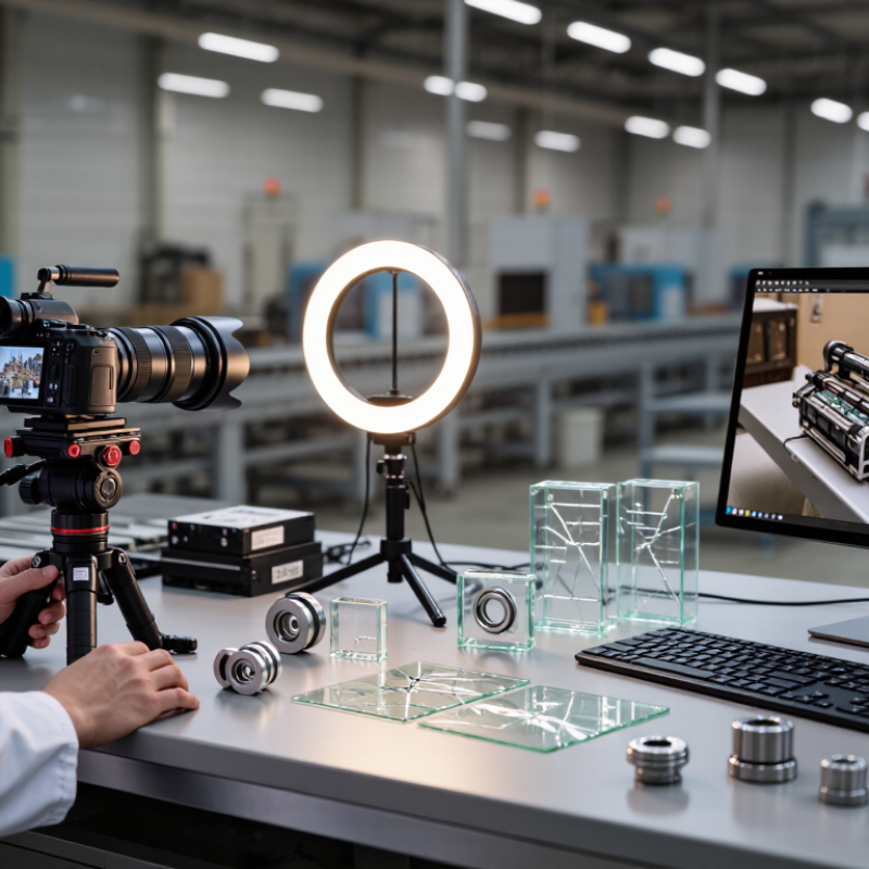
Start by defining what the inspection must catch. A tool for finding missing parts may not reveal hairline cracks or uneven coatings. List the defect types, their smallest acceptable size, and where they appear. A scratch near an edge can be harder to detect than one on a flat surface.
Then match those goals to real production conditions. Measure the part, working distance, available space, and line speed. Check whether lighting creates glare on glossy materials or weak contrast on dark ones. Resolution matters, but so do field of view and depth of field. A high-resolution image is not useful if the whole part cannot stay in focus.
Use representative samples, including borderline defects, when testing a system. Record how often it misses defects and incorrectly flags acceptable parts. Test under normal shifts, not only in a clean demonstration area. Dust, vibration, and changing ambient light can affect results. Consider how inspection data will be stored and reviewed, especially when process trends matter. It is easy to overstate requirements before seeing real samples. That assumption can be wrong. Refine the goals after trials, and document why each change was made.
Optical inspection tools serve different purposes, so match the tool to the feature you need to see. A stereo microscope gives depth for examining solder joints, small components, and surface defects. A digital microscope displays images on a screen and can simplify measurement or team review. For narrow cavities, a borescope provides a view without dismantling the entire assembly. Optical comparators project a part’s outline, making them useful for checking dimensions and profiles. Machine vision systems inspect moving products and can flag repeatable visual differences.
Tips: Define the smallest defect you must detect, then check resolution, field of view, working distance, and lighting. Test the tool with real samples, including clean parts and known defects. Glare can hide scratches, while poor contrast can make edges difficult to measure. Keep reference images and calibration records for consistent results.
A frequent selection mistake is choosing the highest magnification available. More magnification can reduce the visible area and slow inspection. Consider how operators will position parts and record findings during a normal shift. Some samples may still need manual review; no setup catches every defect reliably.
Choosing optical inspection tools starts with the defects your team must detect. Compare resolution, field of view, working distance, and inspection speed. A higher pixel count does not guarantee better results. The camera must capture the smallest relevant flaw across the required area. Check repeatability, too: can the tool measure the same feature consistently across several passes? Ask for sample images or run a trial using real parts, including dull, reflective, and slightly damaged surfaces. A specification sheet can still mislead.
Accuracy depends on more than the sensor. Lens quality, lighting, calibration, and part positioning all affect measurements. Compare stated accuracy with repeatability, and clarify how each figure was tested. If a dimension is critical, check performance across the full measurement range, not only at the center of the image. Small differences matter. Operating conditions need equal attention. Measure available space, line speed, vibration, ambient light, dust, and temperature near the inspection station. A setup that works on a clean lab bench may struggle beside a warm production line. It is tempting to choose the most precise tool, but maintenance, operator training, and inspection time can change the practical result. Leave room for trial runs; the first setup may need adjustment.
| How to Choose Optical Inspection Tools for Your Business? — Compare Key Specifications, Accuracy, and Operating Conditions | |||||||
|---|---|---|---|---|---|---|---|
| Tool Type | Best Suited For | Typical Magnification or Field of View | Dimensional Measurement Capability | Indicative Accuracy Considerations | Sample and Workflow Requirements | Operating Conditions | Key Advantages and Limitations |
| Stereo Microscope | Three-dimensional surface inspection, assembly checks, solder-joint viewing, and general visual examination. | Commonly about 5×–50× total magnification, depending on the optical setup. | Primarily visual inspection. Dimensional readings require a calibrated reticle or measurement attachment. | No inherent dimensional accuracy. Results depend on calibration, focus, viewing geometry, and operator technique. | Works well with larger or irregular parts that can be positioned by hand; specimens generally do not need to be sectioned. | Use a stable bench, consistent illumination, and a clean optical path. Control vibration when inspecting at higher magnification. | Provides natural depth perception and flexible viewing. Measurements are less repeatable than with dedicated metrology systems. |
| Digital Microscope | Documenting surface features, reviewing defects, and sharing images for inspection or training. | Varies widely by lens and sensor; field of view and on-screen magnification depend on the display and working distance. | Can measure image features when the system is calibrated at the relevant magnification and working distance. | Accuracy is setup-dependent; calibration, pixel scale, lens distortion, edge definition, and measurement software all matter. | Parts should be held steady and positioned within the calibrated field. Reflective or transparent surfaces may need adjusted lighting. | Consistent lighting and working distance are important. Avoid vibration and recalibrate after changing lenses or optical settings. | Easy image capture and record keeping. Digital zoom does not add optical detail, and image-based readings need a validated calibration. |
| Measuring Microscope | Measuring small features such as holes, edges, slots, and pitch distances on precision components. | Often uses interchangeable objectives, commonly in the approximate 10×–100× range. | Direct optical measurement using a calibrated stage, crosshair, or measurement scale. | Well-maintained systems can support micrometre-level measurements; actual uncertainty depends on stage quality, optics, calibration, and operator technique. | Best for parts that can be securely placed on the stage and brought into focus. Edge selection should be consistent. | Use a rigid, level surface and stable ambient conditions. Clean the stage and optics; control vibration and temperature changes for tighter tolerances. | Useful for small, precise features. Manual alignment and focus can take time, and measurement is less convenient for complex 3D shapes. |
| Optical Comparator (Profile Projector) | Checking two-dimensional profiles, angles, radii, and contours on machined or formed parts. | Common projection lens magnifications include approximately 10×, 20×, 50×, and 100×. | Measures projected outlines using a screen scale, overlay, or digital readout. | Accuracy varies by instrument, lens, screen condition, calibration, and edge interpretation. Confirm the maker’s stated accuracy for the selected configuration. | Parts need a clear, stable silhouette and suitable fixturing. Transparent, highly reflective, or irregularly positioned parts may be harder to assess. | Keep the optical path and screen clean; use stable fixturing and controlled lighting. Avoid vibration that can affect edge readings. | Fast for profile comparison and operator-friendly for 2D checks. It does not capture full 3D geometry, and manual readings can vary. |
| Video Measuring System | Repeatable non-contact measurement of two-dimensional features, including hole patterns, spacing, and part outlines. | Field of view depends on the lens and sensor; systems may offer multiple objectives or zoom settings. | Software identifies edges and calculates dimensions from calibrated images; some systems also include a motorized XY stage. | Performance is model- and setup-specific. Check stated measurement uncertainty or accuracy across the working volume, not just image resolution. | Parts must fit within the field or be measured through programmed stage movements. Reliable edge detection requires suitable contrast. | Use a stable, level surface and consistent lighting. Secure the part, keep optics clean, and follow calibration and temperature guidance. | Supports repeatable routines and digital reports. Transparent, reflective, or low-contrast edges may require lighting adjustments or manual review. |
| Selection note: Accuracy figures are not universal specifications. Compare published measurement uncertainty for the exact instrument configuration, working range, and test conditions. Verify performance with traceable calibration and representative parts before using results for acceptance decisions. | |||||||
Choose optical inspection software that matches the decisions your team must make on the line. Can operators adjust inspection recipes without engineering support? Can the system store images, flag defects, and link each result to a lot or serial number? Test it with real parts, including reflective surfaces, minor scratches, and changing light. A clean demo can hide messy production details. Check whether reports fit existing quality reviews and whether staff can retrieve evidence quickly.
Workflow matters as much as image quality. Map how a part moves from inspection to rework, acceptance, or escalation. Define who reviews uncertain results and how false rejects are recorded.
Deloitte and MAPI’s 2019 smart factory study found that 86% of surveyed manufacturers expected smart factory initiatives to drive competitiveness within five years.
That expectation makes integration worth testing, not assuming. Confirm data formats, machine interfaces, user permissions, and how downtime is handled.
McKinsey’s 2015 IoT report projected factory applications could create $1.2 trillion to $3.7 trillion in annual value by 2025; it was a forecast, not a measured outcome.
Start with a limited pilot. Track review time, missed defects, and reinspection rates. I would still expect a few awkward handoffs during rollout. That is useful evidence.
A suitable optical inspection tool should perform well on your actual parts, not only on a clean demonstration sample. Prepare representative pieces, including common defects, acceptable variations, and difficult surface finishes. Run each tool under the same lighting, speed, and inspection criteria. Look closely at small scratches, edge chips, and repeatability across several operators. A single successful scan proves little. Consistency matters.
Record more than detection accuracy. Note inspection time per part, setup changes, false alarms, and how often an operator must intervene. Ask the supplier to test your sample parts, then keep the results and conditions for comparison. If performance changes with lighting or part position, that matters. It may not be obvious during a short trial.
Calculate total cost of ownership over a realistic service period. Include purchase price, installation, training, software, calibration, maintenance, replacement lighting, and production downtime. Estimate labor saved, but use measured inspection times rather than optimistic projections. A lower-priced tool can cost more if it needs frequent adjustments or slows the line. Some costs are hard to predict. State your assumptions, and revisit them after a pilot; early estimates are rarely perfect.
Quality Commercial LED Lighting specializing in LED Tubes, LED Bulbs, LED Troffers, LED Door Kits, LED Retrofit Kits, LED Panels, LED Spot Lights, LED Wall Packs, LED Lamps, LED Drivers, LED Accessories, LED Lights, LED Sales, and LED Manufacturing. Headquartered in Atlanta, Georgia, USA.