
What Is Automotive Stamping Tooling and How Does It Work?
Automotive Stamping Tooling is the press-and-die system that turns flat metal sheet into vehicle components. It shapes parts such as door panels, brackets, hoods, and structural reinforcements through operations including cutting, bending, drawing, and piercing. In a typical press line, a sheet blank enters a matched set of dies. The press applies force, and each station performs a defined operation. Some lines use one die for several steps; others move parts between dedicated stations. The choice depends on part geometry, production volume, material, and quality targets.
The scale is substantial. OICA reported approximately 93.5 million motor vehicles produced worldwide in 2023, a figure that helps explain why repeatable, high-volume forming matters. It does not, by itself, measure stamping demand; vehicle designs and manufacturing methods vary. Still, a poorly aligned die can leave visible marks, uneven edges, or dimensions outside specification. Small errors travel. Engineers therefore consider die design, press capacity, lubrication, sensors, maintenance, and inspection together—not as separate concerns. Advanced high-strength steels and lightweight materials can make forming more demanding, requiring careful trials and adjustments. A tooling plan may look sound on a drawing yet behave differently on the factory floor. That gap deserves attention. This introduction examines what the tooling includes, how stamping works, and which practical factors influence part quality, production speed, and cost. OICA’s production statistics provide context; part-specific decisions still require engineering data and validation.
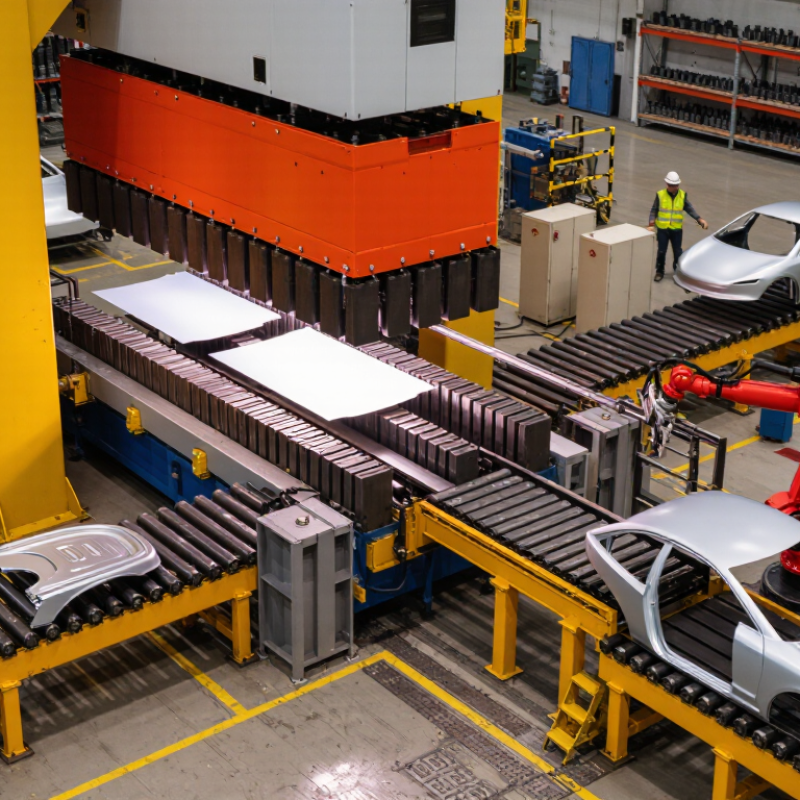
What Automotive Stamping Tooling Is and What It Does
Automotive stamping tooling is the set of dies and supporting components used to shape sheet metal into vehicle parts. It helps form panels, brackets, and structural pieces with repeatable dimensions. A typical tool has an upper die, a lower die, punches, and a blank holder. Each part has a job.
During a press cycle, the sheet is placed between the die halves. The press closes, and the punch pushes metal into the die cavity. Depending on the design, the tooling may cut, bend, draw, or pierce the sheet. Some parts pass through several stations, with each station performing one operation. A sharp cut edge matters. Burrs or uneven forming can affect fit during assembly.
Tooling also controls how metal flows. Draw beads and carefully shaped surfaces can reduce wrinkles, tearing, and unwanted thinning. Yet the first setup is rarely perfect. That is normal. Engineers may adjust clearances or pressure after checking sample parts, though every change needs careful measurement. Regular inspection helps catch wear, loose fasteners, or damaged cutting edges before they create inconsistent parts. A useful tool does more than shape metal; it supports stable production, while still requiring attention from skilled people.
| What Is Automotive Stamping Tooling and How Does It Work? — What Automotive Stamping Tooling Is and What It Does | |||
|---|---|---|---|
| Dimension | What It Is | How It Works | Automotive Example or Purpose |
| Definition | A purpose-built set of tools, commonly called a die, used with a press to form or cut sheet material. | The press drives the die’s working components together, applying force to sheet metal held and guided by the tooling. | Produces repeatable body and structural parts such as doors, brackets, floor panels, and reinforcement members. |
| Typical input material | Flat sheet or coil made from formable metals, including steel and aluminum alloys. | Material is fed into the die manually, as a blank, or automatically from a coil, depending on the production setup. | Material selection depends on part design, strength requirements, weight targets, and forming characteristics. |
| Punch and die | The punch applies force to the material; the die provides the corresponding opening or forming surface. | Their controlled movement shears or reshapes the sheet. The working surfaces and clearance are designed for the operation and material. | Used for cutting openings, trimming edges, and forming part features. |
| Blanking | A cutting operation that separates a flat piece, called a blank, from sheet or coil. | A punch presses the material into a die opening, separating the blank from the surrounding stock. | Creates the starting shape for a formed panel or component. |
| Piercing | A cutting operation that makes holes or other openings in a workpiece. | Punches cut through the sheet, while the removed material, or slug, passes through the die opening. | Creates holes for fasteners, access, or later assembly operations. |
| Bending and flanging | Operations that change the angle or turn an edge of the sheet without cutting out the whole part. | Forming surfaces guide the material around a radius or along an edge to create the required geometry. | Forms mounting edges, hems, and stiffening features, subject to the part’s design and process requirements. |
| Drawing | A forming operation that pushes a flat blank into a cavity to create a deeper three-dimensional shape. | A blank holder controls the sheet while the punch draws material into the die cavity, helping manage material flow. | Used for shaped panels and other parts with depth, such as certain enclosures or body panels. |
| Stripper and blank holder | Tooling elements that hold or control sheet material during cutting or forming. | A stripper helps release material from a punch after a stroke; a blank holder restrains the sheet during drawing. | Supports consistent feeding, part release, and material flow. |
| Guides and alignment features | Guide posts, bushings, pilots, and related features that help align die sections or locate material. | They maintain the intended relative position of the die components and help register the strip or blank. | Important for repeatable feature location and reliable operation over successive press strokes. |
| Progressive die | A die with multiple stations that perform different operations as a strip advances through it. | Each press stroke advances the strip; successive stations cut or form features until the finished part is separated. | Suitable for parts that can be made through a sequence of operations while remaining connected to the strip during processing. |
| Transfer die | A die arrangement in which a part moves between stations during production. | A transfer system moves the workpiece from one operation to the next, allowing separate forming stages. | Used for parts requiring multiple forming steps that are not suited to remaining attached to a continuous strip. |
| Tandem dies | A sequence of separate dies, each installed at its own press station or press. | The workpiece is transferred between dies for successive operations such as drawing, trimming, and piercing. | Can support large panels and multi-stage production sequences. |
| Press and production cycle | The press supplies the motion and force; the tooling determines how that force acts on the material. | On each stroke, the die closes to perform its operation and opens to release or advance the material for the next cycle. | Production setup, press capacity, feed method, and die design must be compatible with the part and process. |
| Quality and maintenance | Inspection and upkeep of working surfaces, alignment, clearances, and material-feed systems. | Wear, damage, or misalignment can affect dimensions, edges, and forming consistency; maintenance helps keep the process stable. | Checks commonly focus on part dimensions, burrs, surface condition, and reliable die operation. |